


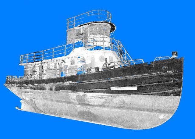
 Using the FARO LS880 Laser scanner, Geospatial Survey Solutions Ltd (GSS) and Deri Jones & Associates Ltd (DJA) were asked to carry out a 3D survey of an existing tugboat hull in preparation for extension and re-modelling. A day was spent scanning the vessel and a CAD model accurate to within 5mm created from the scan data. This model was then used as a reference to create the plating, frames and girders required to extend the vessel.
Tugboat History
 Built in the early 1950's for the US Navy, this American tugboat will be extended and re modelled to create a luxurious explorer yacht for its owner. Very few original drawings exist for the vessel and to carry out the design of the extension, it was decided that an accurate hull model and linesplan were required.
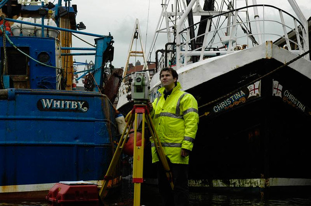
Site Work
DJA carried out a series of 21 scans of the vessel, while it was lifted out of the water on Parkol Marine's drydock in Whitby, N. Yorkshire. Working on a steel drydock in a whistling North Sea wind in the middle of November was no fun for the operators, but the LS880 coped admirably with the conditions.
Processing
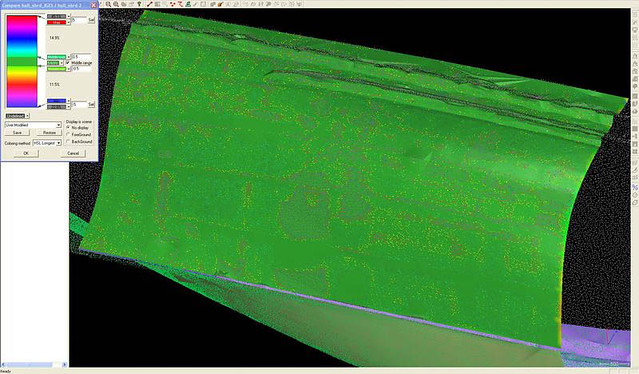 The captured data was processed using FARO scene software to register all of the point clouds together and extraneous data deleted, leaving a clean point cloud of the vessel. The high density point cloud data was then taken in to DJA's VX CAD system, where details such as rotation and squareness of the model were corrected and then checked against manual dimensions taken at the vessel for accuracy.
Once the point cloud had been correctly located in space, it was cleaned and meshed to create a high density STL file – the level of detail visible in this was very impressive, with details such as plate seams, valve inserts and the distortion that happens between frames due to welding clearly visible. Sections were taken through this mesh to create a traditional Naval Architects linesplan, showing transverse and longitudinal sections at different offsets on the hull.
Extension design and surfacing
At a meeting with the owner and Alan MacDougall, the Naval Architect in charge of the renovation of the vessel, the lines plan and 3D STL model were discussed to identify the best location to split the hull and add an extension. Due to the complex curvature of a ships hull, achieving a split line that allows continuity of shape throughout all areas is virtually impossible and using a 3D model of the hull allows informed decisions to be made on the best compromise between continuity of lines and ease of build.
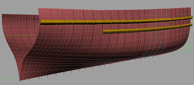 Using VX, the high resolution STL model was used to create a detailed IGES surface model of the centre section of the hull to allow further investigation of the split point and the best method of creating the infill piece for the extension. Once the best location had been identified, a new CAD surface was created that provided a fair surface to use as a reference CAD model. This captured the proposed solution for the extension and would be used to design the frames, girders and other structural requirements for the hull extension.
Since undertaking this project, the owner has decided to use the data we captured to build a bespoke hull, which we will cover in our blog. This video shows the scope and detail that can be recorded using the 3D laser scanners: